PEM Electrolyzers Are Scaling Up: Where Precision-Etched Flow-Field Plates Fit

Updated: Sep 11
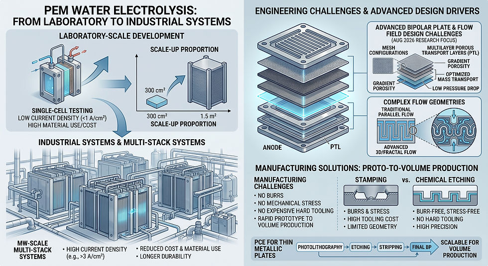
Hydrogen production is moving from laboratory-scale development toward larger industrial systems, and proton exchange membrane (PEM) water electrolysis is one of the technologies receiving sustained engineering attention. As a PEM electrolyzer flow-field plate moves toward production, component design is pushed in several directions at once: higher current density, better mass transport, lower pressure drop, longer durability, reduced material use, and manufacturing methods that can move efficiently from prototype to volume production.
Recent 2026 research reinforces how important the internal flow architecture has become. Studies published in August have examined anode-side structures, mesh configurations, porous transport layers, and alternative flow-field geometries, while industrial programs continue to target lower-cost and more scalable bipolar-plate concepts. For engineers developing thin metallic flow components, this creates a practical manufacturing question: how can increasingly complex channel patterns be produced without adding burrs, mechanical stress, or expensive hard tooling?
Why PEM Electrolyzer Flow-Field Plate Design Matters
Inside a PEM electrolyzer, water must be distributed effectively across the active area while oxygen and hydrogen are removed from the cell. At the same time, the stack must maintain electrical conduction, sealing integrity, mechanical compression, and stable operation under demanding electrochemical conditions. Flow-field geometry therefore influences much more than fluid routing.
Channel width, depth, spacing, manifold layout, open area, and local flow resistance can affect water distribution and gas removal. Poor distribution can create localized operating differences, while excessive pressure drop can increase system penalties. This is why current research increasingly treats flow-field geometry, porous transport layers, catalyst layers, and operating conditions as an interconnected system rather than isolated components.
The Manufacturing Challenge: Complex Geometry in Thin Metal
Many flow-field concepts require repeated channels, narrow lands, manifolds, slots, apertures, alignment features, and sometimes partial-depth structures across a thin metal sheet. Conventional machining can produce complex features, but tool diameter, machining time, burr formation, heat input, and cost become increasingly important as the design becomes thinner and more densely patterned.
Stamping can be highly productive at scale, but it typically becomes most attractive after the geometry has stabilized and production volume justifies hard tooling. During development, engineers may need to evaluate several channel layouts or revise manifold dimensions repeatedly. A process that uses digital artwork rather than dedicated cutting tools can therefore shorten the design-change cycle.
Where Photo Etching Fits
Photochemical etching, also called chemical etching or photochemical machining, selectively removes metal through a patterned photoresist. Because the geometry is defined photographically, the process can produce many features simultaneously across a sheet without a cutting tool contacting the material.
1. Burr-Free Channel and Aperture Features
Photo etching does not mechanically punch or mill the channel edges. This makes it useful where burrs could interfere with stacking, sealing surfaces, thin interfaces, or downstream joining processes.
2. Complex Patterns Without Tool-Path Penalties
A plate containing hundreds of repeated channels is not necessarily processed feature by feature. This can be advantageous for serpentine channels, parallel flow paths, distribution manifolds, fine slots, perforated regions, and other geometries where conventional machining time rises with feature count.
3. Partial-Depth Etching
When the design requires recessed rather than fully open features, controlled partial etching can create shallow flow paths or functional surface structures. The achievable geometry depends on material, thickness, depth, feature spacing, and tolerance requirements, so manufacturability should be reviewed before the design is frozen.
4. Faster Prototype Iteration
Phototooling can be changed much faster than conventional hard tooling. For R&D teams comparing multiple flow-field concepts, this allows several design variants to be evaluated without committing early to a production die.
5. Thin-Metal Material Options
Depending on the electrochemical environment and downstream process, etched components may be developed in stainless steels, nickel alloys, titanium, or other etchable metals. Material selection should be driven by corrosion resistance, electrical requirements, joining method, coating strategy, and stack operating conditions—not by etchability alone.
From Flow-Field Plate to Stack Architecture
The value of an etched plate is often best understood as part of a larger assembly. A single patterned sheet can serve as a flow-distribution element, while multiple patterned layers may be aligned and joined to create more complex three-dimensional fluid structures. Depending on the application, engineers may combine etched plates with diffusion bonding, brazing, welding, coating, sealing, or other downstream processes.
For PEM electrolyzers specifically, photo etching should not be presented as a universal replacement for stamped or formed bipolar plates. High-volume mature designs may favor other manufacturing routes. Its strongest role can be in complex thin-metal geometries, engineering validation, rapid design iteration, specialty flow components, and programs where hard-tool investment would otherwise slow development.
What Recent PEM Research Signals for Component Engineers
A study published in the International Journal of Hydrogen Energy in August 2026examined how anode-side structure, porous transport layer characteristics, water flow rate, and temperature influence PEM electrolyzer performance.Another August study in Fuelinvestigated structured metal-foam flow fields and compared their performance with traditional flow-field approaches. These studies point in the same engineering direction: transport architecture inside the cell remains an active optimization area.
Industrial scale-up is happening in parallel.Plug Power announced a 50 MW PEM electrolyzer order for Australia's Hunter Valley Hydrogen Hub in July 2026, whileEuropean research programscontinue to explore alternative bipolar-plate concepts and production methods aimed at lowering component count and manufacturing cost. The implication for suppliers is clear: future opportunities will not come only from producing more plates. They will come from helping engineering teams manufacture new geometries quickly enough to test, refine, and industrialize them.
Design Information to Provide for an Etched Flow-Field RFQ
For an efficient manufacturability review, provide the metal grade, sheet thickness, overall plate dimensions, channel or aperture dimensions, required etch depth, dimensional tolerances, flatness requirements, annual volume, prototype quantity, surface or coating requirements, and any downstream joining process. A DXF, DWG, STEP-derived 2D drawing, or dimensioned PDF can help identify features that may need adjustment before phototooling.
Precision-Etched Flow Components from Metching
Metching supportsprecision photo-etched thin-metal componentsfor engineering applications that require complex patterns, fine openings, partial-depth features, and rapid design changes. For flow-field development, our role starts with manufacturability: reviewing the relationship between material thickness, channel geometry, etch depth, spacing, tolerance, and downstream assembly requirements before production begins.
If you are developing a PEM electrolyzer flow plate, bipolar-plate subcomponent, porous flow structure, or another thin-metal fluid-management component, send us your drawing and material requirements. We can review whether photochemical etching is an appropriate manufacturing route and identify the features most likely to affect cost, tolerance, and repeatability.
Frequently Asked Questions
Can photo etching manufacture PEM electrolyzer flow-field plates?
Yes, for suitable thin-metal designs. Photo etching is particularly useful for complex channel patterns, apertures, manifolds, and prototype or specialty plates. Final suitability depends on material, thickness, channel depth, tolerance, coating, and stack design.
Can titanium be photo etched?
Titanium can be chemically etched using specialized process chemistry. The required grade, thickness, geometry, and surface condition should be reviewed before production because titanium behaves differently from stainless steel or copper alloys.
Is photo etching suitable for high-volume bipolar plates?
It can be suitable for some designs and volumes, but it is not automatically the best process for every bipolar plate. Mature very-high-volume designs may favor stamping or forming. Photo etching is especially valuable when complexity, thin material, burr-free features, prototype speed, or frequent design revisions are important.
Can partial-depth flow channels be etched?
Yes. Partial etching can form recessed features, but achievable depth and dimensional control depend on the metal thickness, feature width, pattern density, material, and etching process. Early DFM review is recommended.
Key Takeaways
PEM electrolyzer research continues to focus on flow distribution, mass transport, efficiency, durability, and scalable manufacturing. Precision photo etching offers a useful route for complex thin-metal flow structures because it avoids mechanical cutting forces, supports dense patterns and partial-depth features, and allows fast design changes. A PEM electrolyzer flow-field plate should be reviewed early, before channel geometry, material, coatings, and joining requirements are locked into the stack design.

Comments